
Even though the 12BY7A is considered a small signal type, it has ratings more in line with a small power pentode, such as the 50C5. This is due to the original design purpose: a video amp for color TVs. Given the 4.0MHz upper limit for TV video, it takes a lot of current to charge even the very small device capacitances of CRTs. For this purpose, the internal device capacitances are low, and the gm high.
The 12BY7A has also seen quite a lot of applications in ham rigs, either commercial or amateur, usually as oscillator/buffers. Unfortunately, this has made them rare and expensive. As for audio use, there really isn't much.
There are a couple of reasons for that: the 12BY7A requires a fairly high rail voltage. This wasn't a problem as there is lots of high voltage available in a color TV. The other reason is that you seldom need the gain the 12BY7A is capable of producing if your usual sources are CD changers, tuners, sound cards, or TV audio, as all of these produce outputs of 1.0VRMS or so. In applications where you need the gain for low level signals, you can get the same voltage amplifications with small signal pents that don't require the same still plate currents.
In those cases where you do have the rail voltage to support it, the 12BY7A can swing a high output while doing so with good linearity and low distortion. As with any small signal pentode in an audio amp, the best performance comes with the lightest possible plate loading. With this type, that usually means plate loads of around 20K or so, rather than the 100K+ plate loads of smaller types like the 6AU6.
12BY7A Plate Characteristic
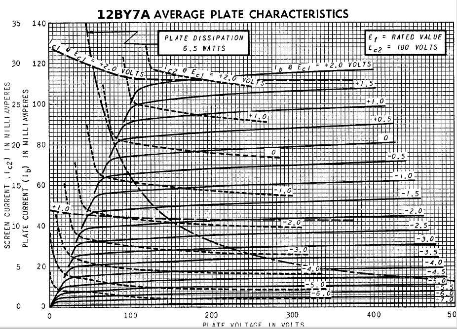
As for most pentode plate characteristics, this one is more apropos to the design od vid amps and other wide band, high frequency circuits. The more linear region is to be found at the bottom, with smaller plate currents, where the gm doesn't vary as much with plate current.
For audio designs, the "plate transfer" curves are a good deal more useful, as you can pick off both screen voltages and Q-Point bias. Getting the screen voltage as low as possible, consistent with input requirements, always helps improve linearity, as you don't want the plate swinging below the screen.
It isn't a type you may ever have to use that often, but when you need gain and large voltage swings, it's a type to consider.
6AU6

The 6AU6 isn't glamorous, and the wrap-around plate doesn't make it especially interesting to look at. Not the least bit glamorous, just a reliable work horse that does just about anything well: CCS duty, voltage regulator error amp service, small signal audio and RF amp. It has a generous VHK= 100V (heater positive) / 200V (heater negative) rating that suits it for both error amp and CCS duties.
As a small signal amp, the linearity is very good, especially if you can get the passive plate load up, and run it at small plate currents, consistent with drive capability of the load.
The 6AU6 is a miniature sharp cutoff pentode primarily designed for use as a high gain radio or intermediate frequency amplifier. Its low grid-plate capacitance and high transconductance make it especially suited for high frequency, wide-band applications. -- GE Spec sheet
Given that the spec sheet doesn't mention audio, the included plate characteristic isn't especially helpful. For doing audio design work, the included plate and screen transfer curves are more useful. From these, one may pick off bias points, screen voltages, and plate current swings to calculate likely low distortion Q-Points. As this would most likely appear in a low level stage, linearity isn't hard to come by for small plate voltage swings. Though these curves were taken with VPK= 250VDC, this presents little problem as the plate characteristic is quite flat for voltages above 80V. Operating at lower voltages might require some adjustments to the screen voltage and/or bias point.
As with any other pentode, there are the usual considerations: microphony since there are three grids inside the bottle, as opposed to one, therefore, more parts that can jiggle. There is also the possibility of increased noise. This is especially vexatious at audio frequencies as such things as cathode flicker noise and screen partition noise decrease with increasing frequency.
There are two other ways to use the 6AU6: as a pseudotriode. This can be done in the usual manner: paralleling the plate and screen. The spec sheet even includes the pseudotriode plate characteristic. This gives a μ= 36, which falls nicely between the gains of types like the 6SN7-oids, and high gain types such as the 12AT7 or 12AX7. Convenient when you need gains that fall between those two types.
Triode Plate Characteristic

Whether to connect the suppressor to the plate or cathode is another gray area: some say better sonic performance is had one way or the other. There is no consensus for this. Changing the suppressor connection doesn't alter the plate characteristic all that much in any case.
The other way to make a pseudotriode is to connect the plate to ground, and use the screen as the triode plate. If the screen spec isn't busted by this, then the plate becomes an internal shield. This would prove useful in electrically noisy environments. It changes the actual characteristic very little since it's the screen, not the plate, which determines the actual operation. In any pentode, due to the isolation of the plate, the plate serves mainly as a pseudo anode that simply collects the electrons at the end of their journey.
Don't overlook the 6AU6 if you decide your design could use a pentode.

I picked up a half dozen of these at the Dayton Hamvention recently. This is an "industrial" type since it has a numerical type designation, as opposed to the alpha-numeric identifiers more commonly known as "consumer" types. It's a singleton, small signal triode. The configuration is decidedly odd. The octal base comes complete with all eight pins in place, though only three of them are connected to anything: two heater connections, and the cathode connection. It seems that this was designed as an avionics type, and the full compliment of octal pins included for extra mechanical stability.
The plain white boxes they come in:

The two top cap connections are by design, as the type originated in the early 1940s, as VHF tech was coming into its own. The top cap connections being to allow for short, low impedance, connections, as a VHF oscillator. Other than that, electronically it is very similar to the 6J5: an excellent small signal audio triode that is basically one section of a 6SN7 dual. It can be used as a direct substitute in any design that requires the 6J5, and they are dirt cheap and available. That's a good thing in case 6J5s become difficult to acquire and/or audiophool expensive. Since I use 6J5s, this was a good acquisition. Some like 'em for their funky appearance and/or as a substitute for the more expensive and harder to acquire glass versions of the 6J5. (There's a whole bunch of audiophoolery concerning the undesirability of metal types.)
If using the 7193, care must be taken with those top cap connections, as transposing the plate and grid connections will result in poofage. The 6J5, unlike the later, hardened, 6SN7GTA-B types intended for TV vertical deflection duty, was never intended to run into significant grid current. A hundred volts or so between the grid and cathode will be a disaster. The connections are clearly visible, so getting them right isn't a problem if you know what you're doing. This could pose problems if doing "consumer" designs for end users who don't know what's inside the glass and couldn't care less.
Otherwise, use 'em like any other type with top cap connections, as the caps fit connectors designed for the small top caps such as the ones fitted on 6BQ6's and other power finals.

This is a vertical deflection pentode for color TVs. It has the 12 pin "Compactron" base, all glass construction, and does not include a top cap connection. The rated PD= 19W. With a modest voltage, a PP pair can give 34W, and with an estimated h3= 3.57%. This would put it in the same category as the 6L6-oids, so far as operating voltages and power output. As for how this actually sounds, that depends on the harmonic "personality" of the distortion. If it's mainly h3, then it won't require any extra help from local NFB: just add enough gNFB to take the "edge" off, and, of course, to improve speaker damping. As with the horizontal deflection types (and the 6L6-oids) the screen voltage rating is limited. This makes UL difficult to implement without OPTs with special tertiary windings. Should local NFB be necessary, it can always be implemented as cathode feedback, or parallel feedback. A stiff (preferably active regulation) Lo-Z screen supply is best for sonic performance. Being that this is a vertical deflection type intended for developing max RMS power, the ratings are on the conservative side. With a bit of spec busting, you can run it hotter than rated, as audio final use is far less demanding. This will get you closer to Class A, and reduces x-over distortion.
It does, however, like a heavier load: 5K44 (P-2-P). The heavier cathode gives the 10JA5 a higher current capability than usual for audio finals. This can help the sonics, especially bass-heavy material. If there's a drawback, it's the odd heater voltage: 10.5V. This being due to the use of series strings operating directly from the AC mains for heater power. It will require an extra heater PTX for that reason.
The 10JA5 looks to be another audio "sleeper", in that audio final use isn't mentioned in the spec sheet. Of course, this isn't a type you'd use in Class A anyway. As with most of these TV tubes, the most linear portion of the plate characteristic is well within red plate territory.
For a 30+ WPC stereo, it's one to consider.


This is a small signal dual triode in the nine pin mini format. From the spec sheet:
The 6BQ7A is a miniature, medium-μ, twin triode primarily designed for use as a cascode radio frequency amplifier in very high frequency TV tuners. In this application, its performance is characterized by low noise figures and high gain.From the piccie, it's obvious that this is indeed a high frequency triode. It has the additional advantage of a high gm, made possible by the comparatively enormous cathodes. These are much larger than those of other small signal types like the 12AU7, 6FQ7, 6SN7, 6C4. The 6BQ7 also has a μ-Factor that falls nicely between types like the 12AU7 or 6FQ7, and the 12AT7.
The spec sheet even includes a composite plate characteristic for cascode operation. What you don't find is any mention of any sort of audio applications. The RCA Receiving Tube Manual does make a concession to this sort of usage, including the 6BQ7 in its example designs for RC coupled voltage amps.

There is something squirrelly about this plate characteristic. Is that an undocumented variable-μ characteristic? This makes it difficult to find a good, low distortion, audio loadline, but it is not impossible. The key is to get the VPK up, and keep the voltage swing well away from the bottom of those curves. This will require either an unusually high rail voltage with passive plate loading, or active plate loading, then good audio performance may be obtained. The 6BQ7 is a good deal more linear than its VHF cascode cousins, types like the 6BK7B, which is hopeless as an audio amp. Whether it's as linear as the more common audio small signal triodes is another matter entirely.
So what good is it? The one thing that brought this type into consideration was the design of an audio cascode subsystem. In solid state practice, transistor cascodes are not that unusual. In hollow state practice, I came up with very little information. Nearly all references to hollow state cascodes were about VHF amps. For audio, it was all for guitar amps, and the emphasis was on voltage gain, not sonic performance. Of course, you like distortion in a guitar amp, as this makes for "tone". Still, there is the solid state practice, since cascoded transistors operate more linearly than do singleton transistors. Was it just that hollow state audio cascodes were "weird", and therefore not used so much?
The usual audio suspects didn't work out so swell. Cascoded 6SN7s didn't have enough gain, and 12AT7s showed a gm rolloff with decreasing current that likewise made them unsuitable for this design. The RCA Manual mentioned the 6BQ7 as a cascode.
This was a case of try it and hear. I designed and built an LTP phase splitter made from two cascoded 6BQ7s. Even though this costs you half your voltage gain, there was sufficient to eliminate an additional gain stage while maintaining sensitivity even when gNFB is included. As to performance, it was quite excellent, producing excellent phase-to-phase balance with an active tail load, and undetectable harmonic distortion. Since the LTP phase splitter is also a differential, it provides a ready gNFB summing node. As an audio cascode LTP splitter/differential amp, the performance is excellent. A singleton 6BQ7 can also serve quite nicely as a triode LTP, especially if you include active tail loading.
The fat cathodes glow nicely as well.
Cascode LTP Example

You do have to watch out when using the 6BQ7A. Pay attention to how the heaters are connected. There are two ways this was done: an internal series connection wherein the heaters are wound with one continuous filament, and those where each heater is individually connected to the heater support pins. The series heater versions tend to be microphonic, and they ring like bells. The parallel heater versions aren't microphonic. That goes with the territory: series heaters are cheaper, and less attention to detail was paid. I suppose they figured that ringing at audio frequencies was not going to be a problem at VHF. The series heater versions are also more susceptible to filament burn-out. That unguarded length of heater filament is the first to heat up. It can flare brightly for a second or two before the rest of the filament has a chance to heat and develop enough resistance to limit the current. Cheap tubes and cheaply made tubes aren't good tubes. Going to ham meets to acquire a stock is well worth it, as you can examine before buying.
There are two other types with different heater voltages:
4BQ7A: 4.2V / 0.6A
5BQ7A: 5.6V / 0.45A
These types were designed for use in TV sets that didn't have a PTX, and used a series heater string to light the VTs. The currents were quite "standard" for series heater operation. Types with odd heater voltages might be more available and/or less expensive. If using with 6.3V heater supplies, just add enough series resistance, preferably split equally between both legs to maintain balance, to drop the voltage to the rated heater voltage.
One last consideration is that the type includes an internal baffle shield between triode sections. This shield needs to remain negative to any cathode inside, or it could start to function as another plate. That could possibly throw off the bias, or lead to instabilities. It may be a problem with some LTP applications if the cathodes go negative.
The 6BQ7 isn't an easy VT to use in audio work, but when you need more gain than a 6FQ7 can provide, but not so much as a 12AX7 or 12AT7, then it definitely meets the design criterion. The cascode LTP splitter/gain stage is pretty much my universal, "go to" front end design. It provides the gain that you would get from a cascade of a 6SL7 LTP DC coupled to a 6SN7 differential stage, and with a greatly reduced input capacitance that would otherwise interact poorly with a high resistance volume control or long cable runs.
This type is a singleton triode with an octal base. As nine pin mini types proliferated during the early 1950s, few singleton triodes were made, and the few that you do find are almost always VHF amp types intended for 400MHz+, running as grounded grid amps. Most triodes were made in pairs, such as the 12A*7 series, or the 6FQ7, 6DJ8, etc. If you need a singleton triode in the seven or nine pin mini format, you will either have to go with a type like the 6C4 (a type that is not recommended as an audio triode, but rather a low power, Class C RF driver/final) or make a pseudotriode from a small signal pentode. (The 6AU6 works nicely for this, and it has a μ-factor that fits nicely between the medium-μ triodes like the 12AU7 and the high-μ types like the 12AT7 or 12AX7).
The 6J5 appeared with the Octal base, and metal envelope. There is also a glass Octal as well, but is much harder to find, and more costly to acquire. Regardless of packaging, the type is a small signal, medium-μ, singleton triode. It is also basically half of a 6SN7. As such, it can be used for some of the same things: small signal voltage amps, QRP finals, cathode followers, and cathodyne phase splitters, and oscillators. The characteristics are also quite linear, making this type a good one for audio amplification where moderate levels of gain are required.

These are nice, linear plate curves indeed. It is easy find loadlines that exhibit very little harmonic distortion. The type has the linearity for small signal amplification, and the plate dissipation that allows for use as a cathode follower for driving moderate currents into difficult loads. The latter does include the grids of PP finals driven from a cathodyne phase splitter.
There is a bit of audiophoolery regarding the type. Some dislike the metal envelope, and have made accusations of all sorts against it. Yes, the metal cans do cost you a few glowey bottle kewlness points, and the paint offers little protection in circuits that use negative rail feed to the cathode, instead of/in addition to the positive DC rail. In such cases, it would be safer to opt for the all-glass version. Otherwise, I don't know what difference it could make, and the auto-shielding of the metal envelope is an advantage for the typically low level signals of small signal work. Unless you can specify a specific need, like the extra insulation or something. Otherwise, it's an unnecessary audiophool premium.
That does bring up one extra consideration: the cathode must never become more negative than the envelope. If it does, then the metal can can work like a second plate, attracting stray electrons. This can lead to, at the very least, increased cathode current and excessive bias. Various parasitic instabilities are also a possibility. The safest thing to do with the metal can is to connect its pin to the cathode pin. It's never a problem when using the type in the most common manner: cathode bias resistor, the plate supplied from the positive, DC rail only.
The other bit of audio mythology is that the 6J5 needs to pull at least 10mA to sound good. This just isn't true, and you seldom need that much plate current unless you're designing some sort of QRP application with it. The 6J5 was designed for low power applications, and the 6SN7 was often used in B & W TV sets as a combination plate coupled multivibrator/power amp for vertical deflection duty. The 6SN7GTB is a "hardened" version made as TV screens grew larger, and the demands on the deflection systems greater.

Here you see the loadline for low current operation. The estimated H2 is virtually non-existent, and in practice this design worked as promised. There was no measurable distortion in evidence, the Twin-T test showed nothing above the noise floor, and subtractive testing showed nothing more than a pure sine wave arising from phase shift. No distortion of any importance.
The main draw back to such operation is that the low plate current drives up the plate resistance. This compromises high frequency performance, with the high frequency -3.0db point coming in at 45KHz. It is trivially easy to get bandwidths a decade larger with any small signal transistor operating at similar voltage gains. Whether or not that makes a difference depends on the application. It definitely isn't how you'd want to operate a 6J5 in a wideband,"DC to Daylight" application.
For the design where the 6J5 was used as a "current trickler", it worked very well indeed. If you need just such a VT, or you have an especially low voltage application, then you don't need to exclude the 6J5 (or the other 6SN7-oids) from consideration.
The 6BQ6 as an audio final came to my attention as a chance result of finding an old article from a Portuguese (Brazilian? -- it was written in Portuguese) ham magazine. This described a simple AM plate modulator that claimed an output of 30W (fixed bias) or 25W (cathode bias) that used a push-pull pair of these VTs. You would expect to see 6L6s or 807s used in this particular application. Why 6BQ6s, and what were they?
The 6BQ6 is a large signal beam former. It has no audio pedigree whatsoever, and the spec sheet makes no mention of its use as an audio final. During the 1950s, screen sizes and deflection angles increased, giving a larger viewing area, and a shorter CRT for more compact TV sets. This development meant that the usual audio finals and RF types became increasingly unsatisfactory for horizontal deflection duty. New types more suited to the task were developed, and one such type was the 6BQ6, in several different iterations for large screen, B & W TV sets.
The 6BQ6, as with all HD types, is capable of pulling big currents through the horizontal deflection coils. This was accomplished by cathodes much larger than those found in comparable audio and RF finals, such as the 6L6-oids. Compare heater voltages and currents:
6V6: 6.3V / 0.45A (2.835W)
6L6: 6.3V / 0.9A (5.67W)
6BQ6: 6.3V / 1.2A (7.56W)
This makes possible a maximum cathode current spec of 400mA. In terms of solid state, that isn't very spectacular, but for a nominally high voltage, low current device, it's pretty good. Other design features include a low voltage capability, made possible by the close proximity of screen grids to the cathode, and that's what you want for drawing big currents through deflection coils, and for operation from transformerless power supplies that derive the working DC directly from the AC mains. The latter consideration has spawned versions of this tube with odd heater voltages for operation in series heater strings.
As an audio final, the high current and low voltage capabilities make for lower load impedances, and therefore, for easier to design OPTs. The lack of any audio final usage requires one to draw up loadlines to find suitable operating points. Here is one such audio loadline:

As you can see, the load is just 1K1 per phase. This is a Class AB loadline, so you would need an OPT with a primary that can match 4K4 (P-2-P) to your speaker load. It's is a good deal easier to manufacture an OPT with excellent high and low frequency performance than it would be for the 10K (P-2-P) load a PP pair of 6V6s need. It's also a convenient value since there are off-the-shelf OPTs that were designed for Class A, PP, 6L6s that match this value. The only drawback to using one of these OPTs is that they are a bit under powered for the 6BQ6.
As for why no audio uses are specced, the plate characteristic tells all. It is not possible to use the 6BQ6 in Class A. The most linear part of that characteristic lies well within red plate territory. You are committed to Class AB, push-pull only. That isn't necessarily a bad thing, though.
If you stick with the usual convention for determining the static plate bias current, you are deep into Class AB. The closer you come to Class B conditions, the more cross-over distortion you have. The estimated H3= 5.0% is barely acceptable. There is something you can do about this. The 6BQ6 was specced very conservatively, since its main purpose is to output max RMS power for hours a day, all the while maintaining a reasonable service life. Audio amplification is a good deal less demanding. If you increase the bias, and bust the plate dissipation spec, the performance improves greatly.

Doubling the bias current to 50mA per plate, makes for 17.5W of static dissipation: exceeding the spec by 6.5W (the 6BQ6 is rated close to the 6V6). This is of no consequence, as you don't get any color on the plates. The RCA gray plates can handle up to 70mA, with just a trace of color. The Sylvania black plates aren't showing any color even at this extreme 24.5W of static plate dissipation. 50mA of bias won't harm this type, even if it's outside of the spec. The increased bias current, and the much lower H3 estimate, does make a noticeable -- and improved -- sonic difference in practice.
As to the sonic performance of the type that had no audio pedigree, in a word: excellent. The 6BQ6 easily matches the performance of the legendary 6V6, and it pumps out more than twice the power. Running open loop, the 6BQ6 doesn't have any of that expected "pentode nastiness" until it's nearly at the point of clipping. There's just an "edginess" or "aggressiveness" to the sound. That would account for why the Portuguese (Brazilian?) hams elected to use it in their plate modulator project (it was an open loop design). 6L6s tend to sound much worse open loop.
The Twin-T test also bears this out. After nulling the fundamental, the residual is almost a perfect sine wave at three times the frequency. There is little higher order harmonic components. Though high fidelity isn't legal on the ham bands, the 6BQ6 plate modulator would indeed sound better. For excellent sonic performance, all that's required is enough gNFB to take off the edge. The 6BQ6, like the 6V6, doesn't require the additional help of local NFB. That is a good thing in that the low screen voltage spec pretty much eliminates Ultralinear. Operate them in full pentode mode with a regulated screen supply. As with any pent that can't run the plate and screen at the same potential, the best sonic performance results when the screen voltage is tightly regulated, and supplied from a source with a very low impedance, as is the case with an active regulator.
The 6BQ6 also seems to be a good deal more stable in operation. It doesn't produce the snivets that are seen with other types, even if you don't include plate and screen stoppers. Even if not strictly necessary, it does no harm to include these anyway. Screen stoppers can be 680Ω/0.5W C-comp resistors. Plate stoppers can be made from ten turns of #18 wire, space wound 7/16ths inch ID, with 100Ω/2W (or four 470Ω/0.5W C-comps in parallel) de-Qing resistors mounted inside the coil. That should take care of any possible instabilities, or tendencies to make RF, due to lay-out issues.
This type appeared early on in TV development. The first iterations were in ST glass. As TV screens got bigger, new versions appeared. The 6BQ6GTA has the small profile, tubular glass envelope. This type has smaller cathodes, and is not quite so robust as later iterations. As such, it will red plate badly if used at the Q-Points mentioned previously.
The 6BQ6GTB has the same small diameter envelope, but does work as described above. The 6BQ6GA has a larger bottle, but otherwise biases identically to the 6BQ6GTB. As for sonic performance, the 6BQ6GA may have a slight sonic edge, but I'm not 100% certain of that. Either version sounds great, and will stand up to the spec busting for long service life in audio amplification applications, which is what we're interested in here. Of course, audio amplification is not the same as horizontal deflection duty, or "brick on the key" RF modes (FM, Packet) either.
The 6BQ6 really is a tougher, higher powered, 6V6. The main difference is the greatly reduced screen voltage spec that precludes Ultralinear, and makes pseudotrioding problematic. As a pseudotriode, since the screen voltage never exceeds the plate voltage, you may be able to get away with running at higher than specced screen voltages without either poofing the screens or plate current run-away. That remains to be seen, if you're so inclined to experiment with it.
The advent of TV sets running transformerless power supplies has also led to the development of *BQ6s that have some odd heater voltages:
12BQ6: 12.6V / 0.6A
25BQ6: 25V / 0.3A
These types were intended for use in series strings, as there was no PTX to provide heater power. That such types exist is beneficial in case the 6.3V version should become harder to acquire, and/or the price becomes excessive. Five years ago, you could get 6BQ6s for under a dollar a pop. Due to inflation, and probably the publication of designs that use the type, the prices have been going up. Still, it's not like audiophool expensive, even for quality that's dubious, of finals that do have that audio pedigree. Availability should not be a problem, since the 6BQ6 was widely used in a great many brands of wide screen, B & W TV sets.
This type is very close to the 6BQ6 in terms of specs and sonic performance. The main difference is that the 6AV5 lacks a top cap connection to the plate. This would be a plus for designers who're leery of plate top caps in audio amps that potentially expose end users to dangerous voltages.
If you can wind your own OPTs, or don't mind paying extra to have custom OPTs wound, other possibilities present themselves. As B & W screens increased in size, new types that could handle the increased current demand were developed. This would include types such as the 6CB5 and 6DQ5 -- both capable of even higher output power.
With the advent of color TV, the demands put upon horizontal deflection subsystems grew even greater: color TV CRTs operate at much higher voltages, require more cathode current, and also had the large screens and deflection angles. To meet these demands, some truly awesome power tubes were developed for increased current sourcing, and power handling.

This beast is the 36LW6: Pd= 40W, Imax= 1.75A
It was one of the last generation of Octal HD finals before the advent of the Duodecar (12 pins) and Novar (9 pins) all glass tubes that began to appear during the early 1960s. Part of this development was to allow for putting more tubes in the same envelope. You had a single bottle that might include two RF pentodes for TV IF amps, or combination power triodes and small signal triodes for vertical deflection duty, or triode/pentodes for sync sep/horizontal deflection time bases. FM demodulator/audio voltage amps and power pentodes were likewise included in the same bottle. It was common to put the HD final and the damper diode in the same bottle.
The 6.3V version has become extremely difficult to find these days since a good many were diverted to ham use as RF finals. Even worse was the diversion to illegal CB linears during the mid-1970s CB craze. These illegal rigs were all too frequently badly designed, and poofed the finals too quickly. However, there are quite a few still available if you go with the odd heater voltages, and the prices aren't exorbitant either. You'll have to either wind your own heater PTXs, or have them custom wound. The characteristics remain the same. This type was also designed for operation from a DC rail derived from a transformerless voltage doubler. The spec sheet mentions that it needs just 280VDC to work, and the published plate characteristic doesn't extend beyond that particular voltage. That would account for the variety of heater voltages. This is a definite benefit for audio design: low load resistance, and the avoidance of high plate voltages.

This looks promising indeed. That's nearly 95W of audio power from a single pair of PP finals, running conservatively, and with a Vpp= 300VDC. It is helpful that the grid voltage swing isn't out of line with the more common audio power pents, as this allows for lower distortion from the front end. A good many power finals for RF use in particular would need to run at twice -- or more -- the DC plate voltage and likely Class AB2 operation. Getting that much audio power would require PP-parallel operation of the more usual audio power finals running Class AB1.
The estimated H3 for this loadline comes in at about 0.2%. That bodes well for sonic performance. Given the low screen voltages, there is another possible way to use this: screen drive. Use a MOSFET source follower to drive the screen grid, with the control grid bypassed to AC ground, and used only to set a Q-Point current. This becomes a type of Class AB2 operation that can boost the output power while maintaining a reasonable plate dissipation. It is also helpful in that the screen current remains low until the Vpk is taken to very low levels indeed.
I'm definitely going to have to give this a go some day.

The 807
The first of the beam formers is also one of the most enduring types: the 6L6. Developed by RCA in the mid-1930s, this type was originally intended for use as an audio final. It included other, then new, features besides the elimination of an actual, physical suppressor grid required to smooth out the screen grid "kinks". This included the now standard Octal base (up to eight pins possible, and with a keyed base for proper socket alignment) and a metal envelope. The latter was made in one of two ways: a glass envelope VT slipped into a metal shield can, or using the shield can as the envelope, with a glass base to bring out the connections. Other improvements was to give the control grid and screen grid the same pitch and wire diameter. By overlaying these two grids, the negative control grid serves to "shadow" the screen, thereby reducing the useless screen current for improved overall efficiency.
Though the metal envelope provided excellent shielding, these types ran very hot. Even the small signal metal envelope tubes get unusually warm. As a result, the Octal base was adapted to the glass envelope. Thus, the 6L6G type appeared. The first had the "ST" profile. The 6L6GT with a tubular glass envelope appeared by the early 1950s. The 6L6 (in its various iterations) proved to be quite successful, and is still in production today.
By the early 1940s, the 6L6 was adapted to the "ST" glass envelope, the then-standard five pin base, and with a top cap connection to the plate. This RF version became the 807. The main drawbacks to the 6L6 are that the highest voltage pin is right next to the lowest. For the usual audio operating conditions, this was of no consequence. It did, however, limit the available power when operating as a Class C, RF final. The top cap is also highly convenient, as this allows the output circuitry to be shielded from the input by the chassis itself. It also allows for plate voltages that would cause flash-overs between the plate and heater pins.
As for the characterizations of the type, the spec sheets cover all operations from Class A1 SE, through Class C. Audio final applications are explained for everything from Hi-Fi through PA and AM modulator duties. Having the AM plate modulator capable of using the same finals as the RF deck was a convenience. For PA and AM modulation, efficiency and power output are more important than sonic performance. The data for efficiency includes Class AB2 and Class B (actually a very deep Class AB2). Fidelity by Class A1 or Class AB1, push-pull. As with any pentode, the SE performance isn't so good as a triode final.
Even though this type boasts some outstanding THD figures (THD= 1.8% for push-pull operation) it has gotten a reputation as being a guitar amp final. Perhaps because that's where most are used these days? The 807 does have a tendency to make lots of nasty, high order harmonic distortion. This shows up when performing the "Twin-T" test. The residual after nulling out the fundamental is quite distorted, resembling a sawtooth wave at three times the frequency. This waveform must contain a lot of harmonics, H5 and above.
While running open loop, 807s do sound nasty: lots of listener fatigue. How nasty depends on the program material, but is always there. This particular deficiency was noted by the type's inventor: O. H. Schade. He recommended local NFB to tame that harmonic nastiness. This is frequently accomplished by "Ultralinear" operation. This isn't possible since the 807 has a very low screen voltage limit. Unlike many audio pentodes, the screen can't be run at the same DC voltage as the plate unless you're going to sacrifice a lot of output. That leaves either cathode or parallel NFB. Schade recommended feeding 10% of the AC plate voltage back to the control grid, anode follower style.
When this is implemented, the 807's sonic performance improves. All that remains is to take off some of the "edge" with some additional gNFB (~7.0dbv does nicely if the rest of the open loop design is well implemented). The nastiness can be tamed, and the type capable of excellent sonic performance. With cathode follower grid drivers, the 807 can easily produce some 30W of audio output, though specced at 26.5W. If you're willing to go Class AB2, you can get 80W or more, which requires increasing the plate voltage to 600VDC, and is not recommended with 6L6s. This wasn't done very often back in "the day", due to the problems inherent with providing suitable grid current from a source with the lowest possible output impedance. That usually meant interstage transformer coupling, and that's not compatible with Hi-Fi since it becomes very difficult to include gNFB, due to the pecular phase performance of any xfmr with ferromagnetic cores. These days, a MOSFET source follower can easily drive the grids positive with very low output impedances.
This type definitely likes to make RF. The spec sheet recommends the use of plate stoppers, either 47Ω or 100Ω, C-comp resistors, or a suppressor coil. The latter can be ten spaced turns with an ID= 7/16 inch to provide about 1.0μH of inductance. This is low enough to be of no consequence at even the highest audio frequencies. The coil can be "de-Q'd" by paralleling it with a 100Ω/2W C-comp resistor (or four 470Ω/0.5W C-comps in parallel. Mount the resistor(s) inside the coil. The plate stopper needs to be mounted right at the top cap connector, as is the case with any stopper resistors or coils.
The 807 also likes to make "snivets" when operated in Class AB. When one final goes into plate current cutoff, this triggers a damped Barkhausen oscillation. The frequency being determined by the leakage inductance and stray capacitance of the OPT (usually 60KHz+). The fix here is to include screen suppressors. 1K5/0.5W, C-comp resistors should be soldered to the screen pins with the least lead length. These stoppers will prevent the snivets. (The other possible cure would be a slight positive bias on the beam formers, but that's not possible since these are internally connected to the cathode, and not brought out to a pin.)
If the design work is done correctly, and attention paid to details, there is no reason not to use 807s for Hi-Fi work.
One other application that is seen quite frequently is the use of the 807 in pseudotriode mode as a series pass voltage regulator.

The 6BG6 TV HD Final
The original type proved so useful that it spawned other spin-off types, of which I've discussed one. The 1625 is the 12.6V heater version of the 807. It has the same shape and size, but uses an uncommon seven pin base, presumably to keep people from sticking the wrong VT in the wrong hole.
The 807 also proved useful as a horizontal deflection PA for B & W TV sets (before screens got too big, that is). It was desirable to have an Octal version, and so the 6BG6 is the Octal "807". Internally, and electronically, the types are the same. You could consider the 6BG6 to be an Octal 807, or a 6L6 with a top cap. As with the 807, the top cap keeps the high voltage well away from any low voltage points to prevent flash-over. The 1625, 807, and 6BG6 will all work in any circuit designed for the 6L6.
One thing that needs clarification is the oft stated notion that the 1624 is a "DH" 807. It isn't, as the 1624 was designed for a very specific application: mobile transmitters. Being a DH type, the filament could be turned off during receive and/or monitoring to save battery power. It's an RF type from the get-go, and was intended for Class AB, B, or C. At Vgk= 0, the plate current is quite low, under 100mA, and it won't produce any more than ~10W as a Class AB1, push-pull amp. You can get a bit more power at half the voltage from a pair of 6V6s or 6AQ5s. The 1624 must be operated as a Class AB2 amp in order to get the most out of it. In that case, it gives just a bit less than what a pair of push-pull 807s will provide. If there is a similarity, it's that the 1624 also boasts of some excellent THD performance if driven from a sufficiently Lo-Z grid driver.


